Preamble
For your visible fiber optic light guide projects, it is imperative to choose your LED light source carefully. Most of the time, we can be satisfied with light sources existing on the market if we do not have particular requirements such as compactness, advanced optical characteristics, luminous efficiency, wavelength. This light source connected to the light guide allows light to be shifted to one or more points in often restricted spaces.
The luminous efficiency of a light guide is closely linked to its coupling with its light source.
In the industrial sector, discreet light sources at reasonable prices are sought after if volumes are expected. In this case there is no other choice than to design a light source for its own use with the expected light guide.
Defnition of light source specifications
These specifications must be determined by the use of the light guide with expected light requirements (wavelength, lighting level) and space constraints.
This first expression of need must make it possible to select :
- Nature of the light guide: illuminating optical fibers (light point at the end of the fiber) versus diffusing optical fibers (diffusion of light along the fiber)
- Type of optical fiber: PMMA plastic fibers, glass fibers, silica fibers
- Type of LED (white, color temperature, RGB, light output, dimension, etc.)
- Source compactness level
This expression of need must then make it possible to clarify whether this light source is integrated either in its own box or on the contrary in an existing element of an assembly or even in a strip with several LEDs. The first photo shows a light source integrated into its own box, the second the mounting of an LED on a cover, the third the integration of several LEDs with their printed circuit in a profile.
The objective ofthis tailor-made light source is to inject as much light as possible into the optical fiber bundle. The latter is notably characterized by its optical diameter and its numerical aperture. Thus the injected light must be homogeneous on the optical surface of the bundle defined by its optical diameter and must respect the angle of incidence defined by the numerical aperture in order to prevent the light from being refracted at the start of thelight guide, c 'that is to say enter the guide and come out again.
On the other hand, it is important to know whether the light source must be adjusted in light intensity, controlled remotely either by a remote control or by a DMX /DALI type protocol.
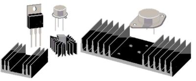
After choosing the LED and its control circuit, you must consider heat dissipation constraints. This element can have an impact on the form factor of the lightsource, particularly if a small radiator must be added. For low power consumption, the box as in the first photo above can act as a heat sink. It isthe same in the following two photos above where the metal support for fixing the light source and the aluminum profile play the role of heat sink.
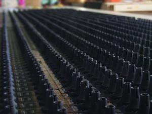
The photos below show small light sources respectively 1W monochrome color (white, red, green,blue, etc.) and 4W RGBW mounted on small radiators with a receiver to accommodate light guides of small optical diameter.
Light source electronic design
A PCB will be designed to integrate the LED, electronic components for current regulation,for controlling the different threshold voltages of an RGB LED. Depending on the definition of the need, the PCB could be connected to a DMX / DALI driver /infrared remote control.
Depending on thecase, this source can integrate a DMX memory if LED programming must be played systematically according to a scenario defined in advance.
Opti-mechanical design
Particular attention will be paid to optical coupling to optimize the flow of light between the LED and the optical fiber bundle. In fact, the angle of emission at the LED output never conforms to the angle of incidence of the optical fibers of the bundle; this characteristic has an enormous impact on the optical efficiency of the light source. Generally we choose a first lens close to the LED to straighten the luminous flux at the LED output.
But generally the insertion of a lens is not sufficient to properly focus the light flux leaving the lens towards the surface of the optical beam. In order to improve the optical efficiency of the source, it is often necessary either to add a new lens or to integrate a reflector having a shape close to an ellipsoid or a paraboloid. This optical design must take into account the dimensional constraints of the chosen LED and the optical diameter of the light guide. This step should make it possible to determine the location of the collector anddefine the mechanical fixing of the receiver.
In the case ofchoosing RGB LEDs, it is necessary to integrate a mixer at the LED output. Asits name suggests, this mixer allows you to properly mix the colors output fromthe RGB LEDs in order to have the color selected on the light guide.
If the light source does not fit into an assembly as a sub-component, it is then necessaryto design an independent box. Its factor form is conditioned by the followingelements :
- Presence of a heat sink other than the case
- Electronic circuits linked to dimming, remote control (remote control,DMX/DALI)
- Presence of an independent memory
- Optical coupling constraints (lenses versus reflector, receiver location)
- Whether or not the source is sealed against water or dust
Please consult usfor our turnkey light guide solutions and service offerings to develop a light source that meets your expectations.
